


How do pneumatic fluid control parts work?
Sep 15, 2025
Leave a message
Pneumatic fluid control parts are essential components in a wide range of industrial applications, from manufacturing and automation to transportation and beyond. As a leading supplier of pneumatic fluid control parts, I am often asked about how these parts work. In this blog post, I will provide an in - depth explanation of the working principles of pneumatic fluid control parts.
Basic Concepts of Pneumatics
Pneumatics is a branch of engineering that deals with the study and application of pressurized air or other gases to produce mechanical motion. The fundamental concept behind pneumatic systems is based on the fact that gases can be compressed and expanded. When a gas is compressed, it stores energy, and when it is allowed to expand, this stored energy is released, which can be harnessed to perform work.
Key Components of Pneumatic Fluid Control Systems
- Compressor: The compressor is the heart of a pneumatic system. Its main function is to draw in air from the atmosphere and compress it to a higher pressure. This compressed air is then stored in a reservoir or tank until it is needed for use in the system. For example, in a large - scale manufacturing plant, a powerful compressor can continuously supply compressed air to multiple pneumatic devices.
- Valves: Valves play a crucial role in controlling the flow, direction, and pressure of the compressed air in a pneumatic system. There are several types of valves commonly used in pneumatic fluid control:
- Directional Control Valves: These valves are used to control the direction of the air flow. They can be manually, mechanically, or electrically actuated. For instance, a simple 3 - way directional control valve can be used to switch the air supply between two different paths. When the valve is in one position, the compressed air flows to one outlet, and when it is switched to the other position, the air flow is redirected to a different outlet.
- Pressure Control Valves: As the name suggests, pressure control valves are designed to regulate the pressure of the compressed air in the system. They ensure that the pressure remains within a safe and desired range. A pressure relief valve, for example, will open when the pressure in the system exceeds a pre - set limit, allowing some of the compressed air to escape and reducing the pressure.
- Flow Control Valves: Flow control valves are used to adjust the speed of the pneumatic actuators by controlling the rate of air flow. By restricting or allowing more air to pass through, these valves can fine - tune the movement of cylinders and other pneumatic devices.
- Actuators: Actuators are the components that convert the energy of the compressed air into mechanical motion. The two most common types of pneumatic actuators are cylinders and motors.
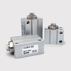
- Cylinders: Pneumatic cylinders are devices that use the force generated by the compressed air to produce linear motion. They consist of a piston, a cylinder barrel, and end caps. When compressed air is introduced into one side of the cylinder, it pushes the piston, causing it to move in a straight line. CD85N25 - 175 - B Cylinder is a great example of a high - quality pneumatic cylinder that can be used in various industrial applications. It is designed to provide reliable and precise linear motion.
- Motors: Pneumatic motors, on the other hand, are used to produce rotational motion. They work by using the energy of the compressed air to rotate a shaft. Pneumatic motors are often used in applications where high - speed rotation is required, such as in some automated machinery.
Working Process of a Pneumatic Fluid Control System
Let's take a simple pneumatic system with a cylinder as an example to illustrate how these parts work together.


- Compression: The compressor starts by drawing in atmospheric air and compressing it. The compressed air is then stored in a reservoir. The pressure in the reservoir is maintained at a certain level, which is determined by the settings of the pressure control valves.
- Valve Operation: When an operator wants to move the pneumatic cylinder, an electrical or mechanical signal is sent to the directional control valve. The valve then changes its position, allowing the compressed air from the reservoir to flow into one side of the cylinder.
- Actuator Movement: As the compressed air enters the cylinder, it exerts a force on the piston. The piston starts to move in a linear direction, depending on which side of the cylinder the compressed air is introduced. For example, if the compressed air is introduced on the rod - end side of the cylinder, the piston will move outwards. This linear motion can be used to perform various tasks, such as pushing, pulling, or lifting objects.
- Return Stroke: Once the desired movement is completed, the directional control valve is switched back to its original position. This allows the compressed air on the opposite side of the cylinder to be vented to the atmosphere, while the other side of the cylinder is filled with compressed air. As a result, the piston moves back to its original position, completing the cycle.
Sensors in Pneumatic Fluid Control Systems
Sensors are also important components in pneumatic fluid control systems. They are used to monitor various parameters such as pressure, position, and temperature.
- Pressure Sensors: Pressure sensors are used to measure the pressure of the compressed air in the system. They provide feedback to the control system, which can then adjust the operation of the pressure control valves if necessary. For example, if the pressure sensor detects that the pressure in the reservoir is too low, the compressor can be activated to increase the pressure.
- Position Sensors: Position sensors are used to determine the position of the pneumatic actuators. They can be used to ensure that the cylinder or motor reaches the desired position accurately. For instance, a position sensor on a pneumatic cylinder can detect when the piston has reached the end of its stroke, and then send a signal to the control system to stop the movement. OVW2 - 06 - 2MHT Rotary Encoder is a type of position sensor that can be used to accurately measure the rotational position of a pneumatic motor.
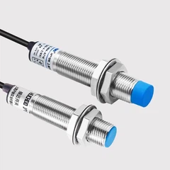
- Inductive Sensors: Inductive sensors are used to detect the presence or absence of metal objects in the vicinity. In a pneumatic system, they can be used to monitor the movement of mechanical parts or to ensure that certain components are in the correct position. IL5004 Inductive Sensor is a reliable inductive sensor that can be integrated into a pneumatic fluid control system for various detection purposes.
Advantages of Pneumatic Fluid Control Systems
- Safety: Pneumatic systems are generally considered to be safer than other types of power systems. Since they use compressed air, there is no risk of electrical shock or fire, which makes them suitable for use in hazardous environments.
- Cleanliness: Compressed air is a clean power source. There are no oil spills or emissions associated with pneumatic systems, which is beneficial for applications where cleanliness is a priority, such as in the food and pharmaceutical industries.
- Cost - Effective: Pneumatic components are relatively inexpensive compared to other types of actuators and control systems. They are also easy to install and maintain, which can result in lower overall costs for the end - user.
Conclusion
Pneumatic fluid control parts work together in a coordinated manner to convert the energy of compressed air into useful mechanical motion. From the compressor that generates the compressed air to the valves that control its flow and the actuators that perform the work, each component plays a vital role in the operation of the system. Sensors add an extra layer of control and monitoring, ensuring the accuracy and reliability of the system.
If you are in the market for high - quality pneumatic fluid control parts, we are here to assist you. Our extensive range of products, including the CD85N25 - 175 - B Cylinder, OVW2 - 06 - 2MHT Rotary Encoder, and IL5004 Inductive Sensor, are designed to meet the diverse needs of different industries. Contact us today to discuss your specific requirements and start a procurement negotiation.
References
- "Pneumatic Systems Handbook" by James R. Cameron
- "Industrial Pneumatics: Technology and Maintenance" by John C. Parr
Send Inquiry